When I lent my services to a collegue who was working on a film about 12 years ago, I was introduced to the world of cnc. I remember watching this huge machining centre milling out a slab of mdf and turning it into a fantastic set of gears. I knew that it would have taken me hours to achieve the same thing with traditional power tools. I decided then that I would invest in a cnc router for my own business Oxenham Design. At that time I could turn on a computer, but even to check email seemed like a crazy set of operations. I persevered and learned every piece of relevant software I could get my hands on. I am now fortunate enough to be using Vectric's ASPIRE software, and Techno cnc routers, which has helped us to create some amazing projects, both in part, or in full. I thought that this blog would be a great place to share "behind the scenes" adventures with the software, materials and equipment we use, as well as the projects we build.

Wednesday 30 March 2011

Texture panel


In the style of samples I started earlier this week, I have designed a new piece for the production company that I can keep on hand for the shop.
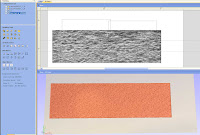
I thought I would make a rusty, beat up metal panel with some interesting components. I started by opening an image of a textured loam wall and converting it to a component. 
I then drew a rectangle and cleared everything ouside it. Next was to duplicate that panel so I would have 2 of them.
I also thought a riveted rail across the bottom would look interesting, so I drew a top and bottom line the height and length of my new rail. Then I drew what the cross section would look like. Using the 2 rail sweep feature, this was done in three easy clicks.
I thought a straight extrusion looked kinda dull after it was made, so I drew 2 new vertical lines at each end of my newly created rail, and drew a wavy cross section. Again I used the 2 rail sweep. Adding this new shape to my first boring rail gives me a whole new shape.


Now to get it all textured, I just turned on the very first textured loam wall shape I had hiding, added my rail I created and now its all textured! A quickly drawn outline around my rail, clearing the texture OUTSIDE my outline, and I've got my exact shape in the texture I need.


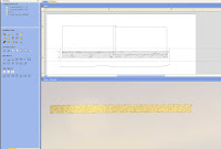
Now for the rivet heads. As in the picture, I just drew a circle the diameter of the heads I wanted, and used the create shape tool to make it a dome. All I needed to do then was to draw a line from the centre of  that rivet head to where I wanted the last one to be placed. I copied the object along the line vector, set my number of heads and that's it! Simple stuff. And by ADDING the dome component, it automatically takes on the texture surface of the model your adding it to. If I had just merged it, it would have no texture, as it would behave like an independant surface.

Tomorrows post should wrap up the software end of this sample, then on to painting it!


JO


Friday 25 March 2011

Cross section part 2


 Here's the second part to the cross section pseudo lesson I started yesterday.


 I then saved this new component and re-opened the original trough model. I then imported the sliver model we just made and oriented it in the direction I needed it, as in the picture below.


So now I have 2 models in our project. I selected the sliver piece and clicked the "create vector" boundary tool. This gives me an outline vector of the sliver. I then lined up the newly created vector shape with our end cap vector in the 2d window.


Then I used the scissor tool to trim out all the unwanted lines, making the final shape.


Now we just need to add texture to the end cap! I brought in the original wood image again and deselected the trough component so I wouldn't do any damage to it. I then converted the image to a component, selected the end cap, then cleared the area outside the selected vector. This gets rid of all the texture except for on the end cap. I also used the "create shape from vector" and added 1/2 to the base of the end cap to give it the thickness I need. There you go, I now have a profile on the end cap that will line up with the end of the trough board with less work than trying to shape it after it's all glued up in the real world.
 JO

Wednesday 23 March 2011

A cross section of sorts ( warning, may cause Aspire acuteness)


I thought I would post today about a process in Aspire that I use quite a bit. We have some upcoming projects that we might be using it for, and I thought I would get a jump on the computer end of it. Sometimes we need a cross section of one component to mate with the profile of another piece. 
In this example I used the two rail sweep and a cross section(the concave c-shaped vector is the cross-section and the top and bottom lines are the 2 rails) This gave me the above trough model. If you haven't done much in this software, just study the pic and it should make sense :) Now that I have the "base shape" I can add our woodgrain texture to it. I imported a custom woodgrain image I made and applied it to the trough.

I then shrunk down the "spikey" texture and smoothed it a little. These simple steps are nothing more than a couple of mouse clicks, very easy stuff. The below picture shows the results of these two steps.

I need two parts to this model in real life. The front "trough" board I created, and an end cap on the right side.
Being that we will just be butt joining them together, I want the software and router to do all the work in making them match. This will save considerable hand finishing after the parts are glued together. I then drew the "end cap" square, which is the second part to this model. To get an accurate cross section, I drew a rectangle box around the whole component, but left a 1/16" space on the right side.

This is the part where you save the model!!! After saving I cleared the area inside the vector box I drew. This left a tiny sliver of the end of the board.

I will finish posting the rest of this tomorrow, It's off to a good start!


JO

Monday 21 March 2011

Mine! Mine!


Just before the Yeti build, I wanted to make a cartoon character. We are now starting to get calls to make life size video game characters, and people are wanting to see real world examples of our work on these types of things. I decided that I would start to make more samples for around the shop, instead of only having what was left over, or returned after a shoot.  I have to say, making cartoon characters real is something that I love. I guess I like the distorted proportions and the fun that they convey. I thought I would post about the process that we went through bringing this guy to life. I started by finding some pretty good reference images on line. I happened to find one of a perfect side view. This always makes it easier to model from. I spent about an hour in our 3d modelling program drawing the various pieces. You'll notice that I left the legs off. This was because we would be using 1/4-20 threaded rods for the leg supports. We would then cover the rods with epoxy putty to blend the legs to the feet.
Next I separated the parts from the model so I could export them individually.
I then imported the parts into Aspire for machining. Because the beaks are symmetrical, I centered them vertically on the zero plane. I was then able to mirror them, which was faster then re-importing the model and flipping it. The feet were relatively flat on the bottom, so I could just slam them down to the zero plane.

I ran a roughing pass on these parts with a 1/4" endmill because I am going to cut them from rigid PVC plastic for the strength. This plastic is pretty hard and it would be faster than nibbling away slowly with just a finishing pass. The roughing pass was offset from the model by .040, so there would be enough material left for the finishing pass. The finish pass was done with a 1/4" ballnose cutter. I was very happy with the results so there was no need to run a smaller cutter.

The body was imported and centered on the zero plane as well.  Aspire has some pretty powerful sculpting tools available in it. I used the smudge sculpting tool to better define the creases on the wings and applied an overall smoothing filter to remove the small triangulated facets that occur when exporting in the STL format. Again I just mirrored the body over because both halves are symmetrical. As I needed them to line up perfectly, this way always works for me. The last step was to machine these on our router out of HDU sign foam. This stuff is great. If you ever get a chance to use, do it. It's dense and carves like butter! We glued the two halves together with urethane glue, using super glue to tack the halves so they didn't push apart when the glue expands. A couple of black cabochons for eyes and some paint and he's done!  I love this guy! I think I'll perch her on a shelf and spill some white paint on the floor under her.

JO

Monday 14 March 2011

Ships Ahoy, sort of.


Saturday was the start of another neat job. We were to supply a 4X8' panel that was to look like a section of an old weathered ship. Complete with rusty bolt heads and ring cleats. Another fun job with the cnc router! We started this build by picking up 20 or so pine planks. We got clear pine so there would be no knots that might fall out. What a disaster that would be for a ships hull! Our panel is smaller than it will appear in the final billboard ad. They will scale it in post to what size they want to use.  I started out by opening a new model in Aspire the size of 5 of our planks stacked edge to edge. Then I used a photograph of wood that I have, and imported it into my model.

I can scale the woodgrain image in Aspire as easily as any image editor, so this makes it remarkably simple. The next step is to convert this image to a component. A component in Aspire is just another name for a 3d model.
 When you convert an image to a component, Aspire changes the image from colour to a greyscale version. After this, the software assigns heights to each of the grey pixels in the picture. Black is the lowest in depth and white is the highest. All the other greys are in between those absolutes. This however can make the 3d model a little spiky. The trick here is to apply a smoothing filter on the model. I applied a maximum smoothing filter and then scaled my whole relief to .100". We were only using 1/2" pine, and wanted to make sure the planks wouldn't get to thin.
This whole process has really only taken me less than 5 minutes already. I then toolpathed the whole model with a 1/2" ballnose cutter. Our Techno cnc router has 3 high power servo motors that move the cutting head all around the 5X10' machine bed. By selecting a machine that uses servo motors instead of stepper motors, it allows us to cut with an accuracy of  .004" as well as run it at speeds of up to 800 inches a minute. This is essential as most of our deadlines are VERY short. The combination of using the biggest cutter that the model detail allowed, and running our machine full tilt, let us machine the 5 stacked planks in 13 minutes. 13 minutes X 4 sets of planks = 52 min in total. In less than 1 hour, all 20 planks had a weathered surface, identical to the picture we started with. The next step was to run a wire wheel over all the planks. This would give us the really fine tearout that weathered wood naturally has.
As Jody started the process of staining and colouring the planks, I started making the rusty bolt heads. I took wooden furniture plugs, then heavily textured them with various texture sprays. Next I was on to the rope tie rings. These started as steel eye bolts. As we wouldn't be on set the day of the shoot, I wanted everything that might have to move to be very easy for them to explore new positions with. I didn't want to drill a 3/8" inch hole through the panel for the eyebolts, if the eyebolts might not even stay. The holes however, would be permanent. I decided to cut off the threads to the eyebolts, drill a hole into the bottom, and screw in a cut-off trim screw. At least any holes left by these little screws, would hardly be noticable. The next part was the actual ring. I took 3/8" acrylic rod and heat bent it over a 3" tube. I then heated the acrylic until the surface started to boil. This would make it look VERY rusty and scaly.


The final step was to mount all the weathered planks to the 4X8 sheet of plywood. After that we inserted all our rusty bolt heads, added some rust stains to the planks and voila! a weathered wooden hull section. They will add the wooden rub rail and rings we made when they get it in front their camera lens. I will upload the final billboard ad as soon as they send me a copy in a couple of days.

Friday 11 March 2011

Shoot that thing!


After changing a flat tire in the pouring rain and driving to the tire shop, Jody and I arrived to the shop 3 hrs past when I was hoping to get there. We only had a little bit of hair to go and fingernail painting left. We took care of that pretty quick and loaded him up for his starring role. After a 2 hour journey, we arrived on location and it was still downpouring.


The frozen lake we were shooting on was a slushy snow plateau. I was a little concerned at first because the wind was really starting to pick up, and the yeti was 10' tall. We did put a steel pipe in his back,
and were able to position a grip stand behind him for added wind support. The stand was very well hidden behind his giant girth.
After we got it all assembled, we got to drizzle blood all over him, the actors and  anything else that wasn't
red! It was now time for my guest appearance in the shot. I headed to the cube van where a Sherpa outfit was waiting.

 The weather quickly turned into a blizzard at that point, but at least I was dressed for it. Matt shot pictures for about 30 min, we all changed positions a few times, did some running back and forth and then that was it.
By then I was cold and wet, and Sherpa wardrobe boots are not waterproof at all!

All in all it was a great build. Matt is a great guy who is very flexible to work with. The crew was fantastic, as well as Donna Irvine in the wardrobe dept. It seems a bit crazy that all this was started only 3.5 days ago. Being able to use straight forward, easy to navigate software, our Techno cnc router and our experience in creating weird stuff, we were able to pull off a huge build in an extremely short time frame.


I will post the final picture of the shoot as soon as it becomes available to us.

---Sherpa Jamie

Wednesday 9 March 2011

Quickly taking shape


This afternoon I laid out the rest of all the parts in the computer.Luckily our Yeti will be mostly covered in hair.
This will allow us to use a giant stepover of 70% or so. It should mean that we can be pulling parts off our Techno cnc router fairly quickly. As it turns out we are cutting an entire sheet of parts every 30-40 min. Just what we need, as the ever approaching deadline doesn't seem to be changing!


As the parts have been coming of the Techno, we have been furiously getting them covered with water-based
contact cement. We use this product as styrofoam is so sensitive to the chemicals found in most other adhesives.Plus the dry time is fairly fast when all the fans are blowing on them.

Here is the leg assembly after all the layers have been glued up. You can see the results of the giant stepover we chose to use. Again, it doesn't matter as we still have to apply 20 yds. of fur.

cutting the chest pieces


This morning I was able to set up the chest layers. These were done exactly like face layers were. I imported the the whole front of the chest and using the slice component feature, cut them into 3" layers. I was able to grab each component in the 2d window and move the parts around for a better fit on the sheet.
Then using the fit vectors to bitmap feature, I could define the top of the sheet that I didn't want to toolpath.
Having done that, it was right onto applying the cutter toolpaths. Selecting all the vectors as my cutting boundaries, I picked the 1/2" ballnose cutter from the tool data-base, set up my material parameters and hit calculate. The thing that I quite like about Aspire is how FAST the toolpath engine runs. It was able to calculate all that cutting in just under 5 seconds. And I did time it :) If you look closely at all those blue lines, those are the lines that our Techno cnc router is going to travel, milling away the foam and leaving the final shape.

The final step was to run a cutout pass to release the parts from the styrofoam sheet.

These are the parts run on the simulation in the computer. This is fantastic because I can see exactly what I will have before I even fire up our Techno!

Next up will be all the other parts that need cutting out.

Tuesday 8 March 2011


After bringing in the face portion, and this is where Aspire shines, I was able to slice the model into 3" thick components. We chose 3" styrofoam for 3 reasons. 1 was our under gantry clearance 2 was our cutting tools flute length. I wanted the cutter to be able to cut the material in 1 pass. And 3 was that styrofoam is LIGHT! After moving the components around to maximize our sheet space, I defined where I wanted the cutting borders to be. I obviously didn't want the router to waste time by cutting the flat portions of the top of the material sheet.This was very easily done by selecting a component in the 2d window and selecting the "fit vectors to bitmap" feature. This let me define the top of the sheet and automatically create a boundary vector. I also put a border around the base of the component as well. With our 3 day deadline, these features are indispensable!
 The next step was to apply a toolpath that our router would use to machine the parts. I used a 1/2" ball nose cutter to reduce machining times as the model was definitely large enough that it would still have lots of detail. After running a simulation, I could see that the eyes didn't have the detail I wanted. Easy enough. I drew a vector bounday around each eye and applied a 1/8" cutter tool path to just that area. The final step was a cut out pass.

I have gotten far more efficient with my toolpaths over the years. I purposely stayed away from all the vertical edges of the model by limiting the tool to not going all the way over the edge. All of the vertical edges would be undercuts anyway, so it is way faster to do it this way and just do a final cutout. We still have to do SOME manual labour!